
Flange Ball Valve Manufacturer in China
A quarter turn and a straight-through bore: no valve type you can put in a line resists flow less, and none closes faster. Our Longz ball valves span gas transmission, buried mains, metering stations and high-temperature service. Which one you specify turns on your medium, pressure and temperature — not on a general claim about ball valves.
various types of Our Flange Ball Valve

Our Longz fully welded ball valve is a spherical shell with a single central weld set away from the seat area — so the sealing parts never sit inside a weld heat zone, and there is one less safety-critical weld for you to inspect over the life of the line.

Our Longz high temperature ball valve the sealing element sits in a stainless steel seat ring with a spring behind it, so seat load comes from the spring rather than from assembly preload. As the face wears or erodes in service, the spring keeps driving the seat onto the ball — and once the soft element is gone, the metal seat closes on the ball itself. Your shutoff class holds instead of decaying stroke by stroke, and there is nothing for your crew to re-torque.

Our Longz oxygen ball valve is degreased before assembly and sealed against recontamination in transit; materials are selected against oxygen-service restrictions, and internal surfaces are finished so a fast stream has no burr to heat. Fully open or fully closed, ball and seat are isolated from the medium — in oxygen service that is a safety feature, not a convenience.

Our Longz V-port ball control valve delivers the flow capacity in a smaller body, and a quarter turn does what a multi-turn stem has to lift against line pressure — so your actuator is smaller, lighter and easier to source years later.
Automatic pressure relief structure of Flange ball valve
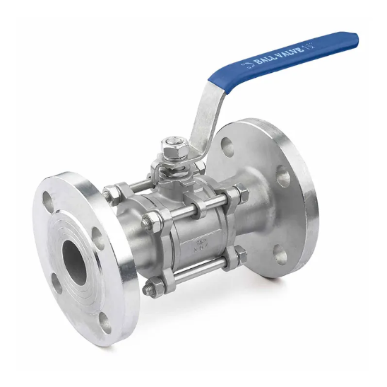
When a flange ball valve needs to shut off the medium, the handle or actuator drives the valve stem to rotate 90 degrees, which in turn rotates the ball. This causes the through hole of the ball to become perpendicular to the pipeline axis, thereby shutting off the flow.
Your Trusted Flange ball valve supplier in China

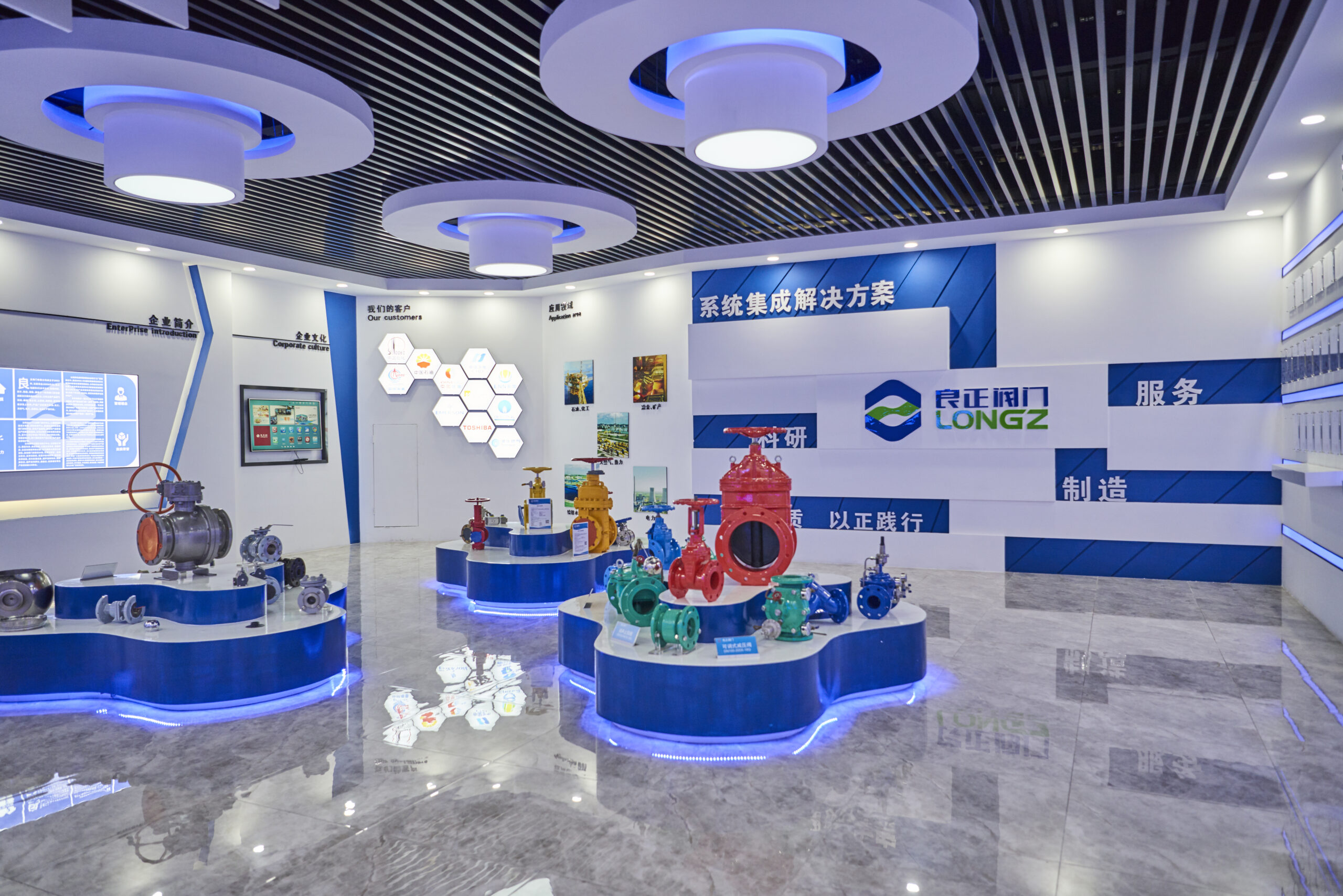
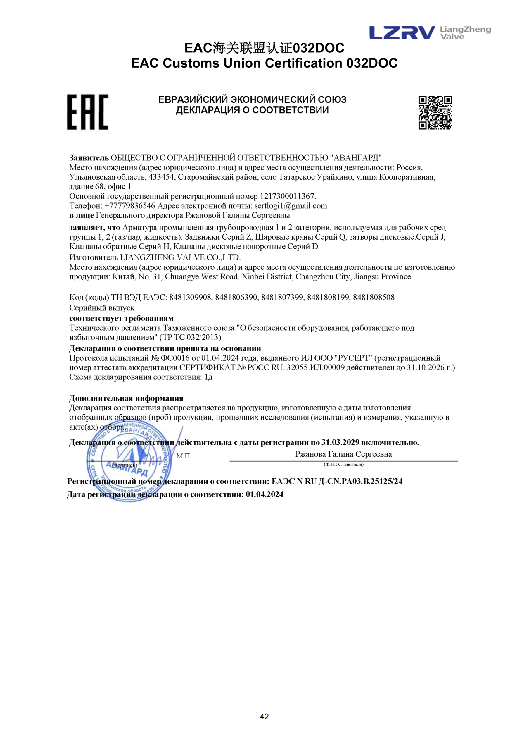
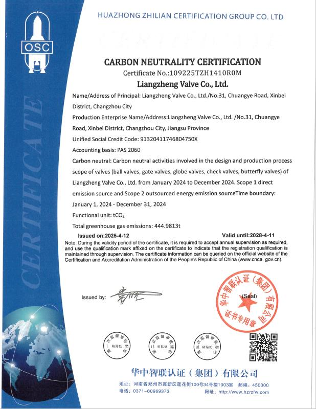
Longz has obtained authoritative quality inspection certificates such as API certification, ISO14001 certification, and German Southwest Germany TUV fire protection certification at home and abroad. The products are qualified and it holds over 50 invention patents and technological innovation patents.
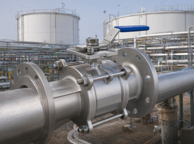
The flange ball valve is used in the chemical pipeline system. It can ensure stable material transportation. Moreover, it can also adjust the flow rate of the medium according to your specific working conditions, thereby meeting the requirements of continuous production and automatic control in the production process.
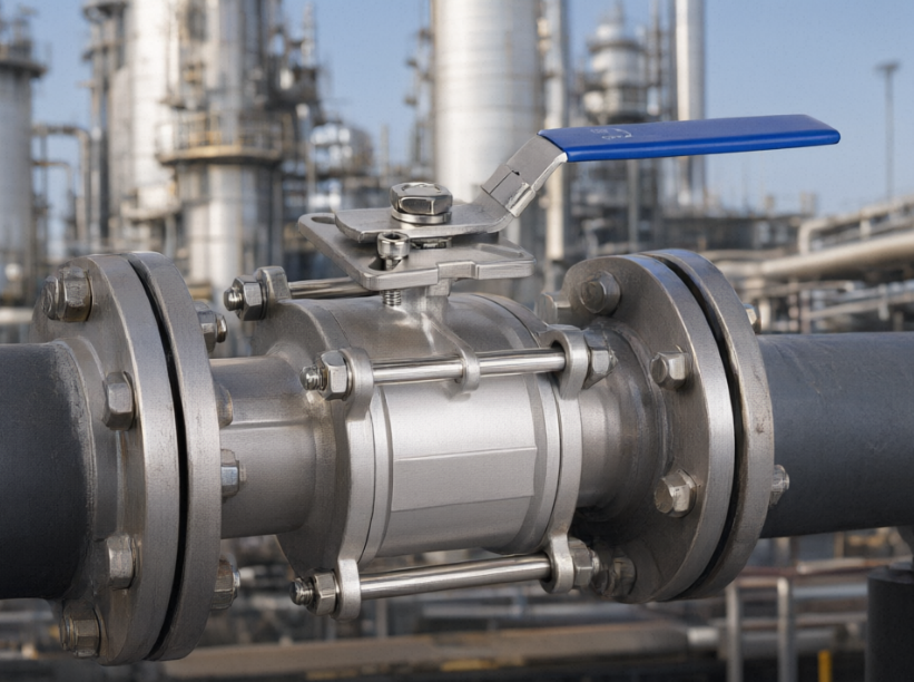
The flange ball valve can enable the quick opening and closing of your natural gas pipeline, facilitating the rapid shut-off of the gas flow during pipeline maintenance, equipment replacement, or sudden leaks, thus ensuring the safety of the system. Moreover, by adjusting the rotation angle of the ball, the gas flow of your pipeline system can be precisely controlled or divided and merged.

The flange ball valve can be used for emergency shut-off and flow regulation of your oil wellhead equipment and gathering and transportation pipelines. It is suitable for harsh environmental conditions such as high pressure, high sand content, and high viscosity. It can ensure the safety and temperature of your oil and gas wellheads and pipeline systems.

The flange ball valve can be used in your pipelines to prevent the backflow of water or sewage, avoiding secondary pollution of the medium or causing water hammer impact on pumps and other equipment. At the same time, it can quickly cut off or regulate the water flow, ensuring the safe operation of the water supply system and fire protection system in your factory.

- certificate
- Dimension Table for Flange Ball Valves
| DN | NPS | L(RF) | L1(BW) | MA | GA | C | H | ||
|---|---|---|---|---|---|---|---|---|---|
| M | M0 | G | G0 | ||||||
| 50 | 2 | 178 | 216 | 161 | 250 | – | – | 105 | 100 |
| 65 | 2 1/2 | 191 | 241 | 178 | 300 | – | – | 130 | 110 |
| 80 | 3 | 203 | 283 | 189 | 350 | 185 | – | 155 | 125 |
| 100 | 4 | 229 | 305 | 214 | 500 | 235 | 280 | 200 | 160 |
| 150 | 6 | 394 | 457 | 265 | 800 | 325 | 280 | 250 | 185 |
| 200 | 8 | 457 | 521 | – | – | 390 | 300 | 278 | 222 |
| 250 | 10 | 533 | 559 | – | – | 445 | 400 | 323 | 280 |
| 300 | 12 | 610 | 635 | – | – | 520 | 400 | 340 | 303 |
| 350 | 14 | 686 | 762 | – | – | 550 | 500 | 375 | 330 |
| 400 | 16 | 762 | 838 | – | – | 580 | 500 | 410 | 355 |
| 450 | 18 | 864 | 914 | – | – | 605 | 600 | 440 | 390 |
| 500 | 20 | 914 | 991 | – | – | 610 | 600 | 495 | 460 |
| 550 | 22 | 991 | 1092 | – | – | 670 | 600 | 525 | 475 |
| 600 | 24 | 1067 | 1143 | – | – | 725 | 600 | 585 | 520 |
| 650 | 26 | 1143 | 1245 | – | – | 760 | 700 | 630 | 560 |
| 700 | 28 | 1245 | 1346 | – | – | 790 | 700 | 645 | 650 |
| 750 | 30 | 1295 | 1397 | – | – | 825 | 700 | 690 | 700 |
| 800 | 32 | 1372 | 1524 | – | – | 870 | 700 | 740 | 745 |
| 850 | 34 | 1473 | 1626 | – | – | 910 | 700 | 760 | 775 |
| 900 | 36 | 1524 | 1727 | – | – | 950 | 700 | 810 | 805 |
| 1000 | 40 | 1753 | 1956 | – | – | 1005 | 700 | 895 | 900 |
| 1050 | 42 | 1790 | 2083 | – | – | 1045 | 700 | 950 | 935 |
| 1200 | 48 | 1995 | 2388 | – | – | 1235 | 800 | 1095 | 1070 |
| 1400 | 56 | 2489 | 2489 | – | – | 1450 | 800 | 1300 | 1250 |
| 1500 | 60 | 2640 | 2640 | – | – | 1550 | 1000 | 1380 | 1350 |
| 1600 | 64 | – | – | – | – | – | – | – | – |
Our workshop has been using a DN150 flange ball valve for over two years now. It operates very smoothly and the valve stem doesn’t feel sticky at all
 EngineerMaldives Gas Company
This flange ball valve has a compact structure. When fully open, the fluid resistance is extremely low, effectively helping us reduce the energy consumption of the pipeline system and lower the pumping costs
 EngineerSpanish Petroleum Company
Sealing is accomplished through the close contact between the spherical surface and the sealing surface of the valve seat. The compressive force is provided by the medium pressure (for floating balls) or by a spring in conjunction with the medium pressure (for fixed balls). Meanwhile, the soft sealing materials such as PTFE undergo elastic deformation under the compressive force to fill in the microscopic irregularities, thereby forming a low-leakage seal.
The conventional two-way ball valve is bidirectional sealed and can be used in both forward and reverse directions. There are no strict flow direction restrictions during installation. However, ball valves with pressure relief holes, single-side sealing, or special valve seat structures should be installed according to the flow direction arrow on the valve body to avoid affecting the sealing and pressure relief functions.
Sealing pressure and medium pressure: The higher the pressure, the greater the clamping force.
Friction coefficient: The material of the valve seat and the surface roughness of the ball have a significant impact.
Friction force of the bearing and packing.
Medium characteristics: Scaling, crystallization or low-temperature freezing can significantly increase the torque.
The applicable temperature for different materials varies. The temperature range is approximately from -29℃ ~ 200℃.