
Orbit ball valve Manufacturer in China
Silt, short fibres and suspended solids score sealing faces on every stroke — and a scored seat leaks however hard you close it. Our Longz rising stem ball valve tilts the ball clear of the seat before it turns, so nothing rubs; a mechanical wedge makes the seal at the end of closing. Your seat is not worn stroke by stroke, and torque stays low.
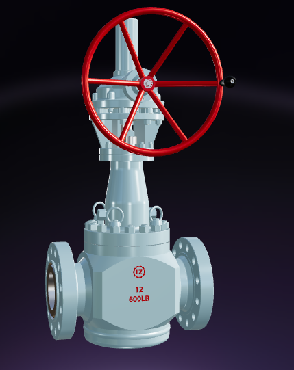
various types of Our orbit ball valve

The floating ball valve has low fluid resistance. Among all types of valves, ball valves have the minimum fluid resistance, and even reduced-diameter ball valves exhibit relatively low fluid resistance. The switch is rapid and convenient. As long as the valve stem rotates 90 degrees, the ball valve completes the full opening or full closing action, making it easy to achieve quick opening and closing.
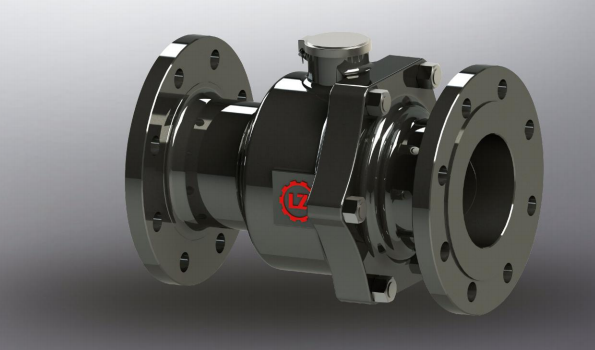
In a riser ball valve, the ball and the PTFE seat form the primary seal under the action of a medium-shaped spring. An O-ring is installed on the back of the seat to assist in sealing. Once the PTFE seat is damaged, the ball forms a metal seal with the valve body under the force of the spring.

The fully welded ball valve adopts an advanced spherical valve body combined with a longitudinal single-weld structural design, providing the valve with sufficient rigidity and strength to effectively overcome stresses caused by construction and terrain variations. The height-adjustable operation extension rod, adaptable to various burial depth conditions, is a more reliable and safe product for gas distribution PE pipelines.
Application Scenarios of Orbit ball valve
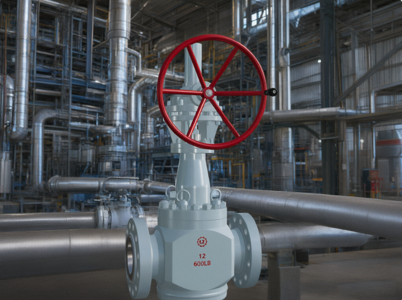
Turn a gearbox valve and you feel the seat dragging. Our Longz orbit ball valve lifts the ball clear of the seat before it rotates, so nothing rubs through the travel and torque stays low. On most sizes that means a handwheel instead of a gearbox, and an actuator sized to the valve rather than to a friction spike.

Every valve costs you something: pressure drop, or weight and space. Our Longz orbit ball valve lets you pick which. Full bore keeps the flow path equal to the pipe, so it takes almost nothing out of your line. Standard bore gives up a little capacity for a smaller, lighter valve. In both, one machined guide groove and guide pin set drives stem lift and rotation together, clearing the ball off the seat before it turns.
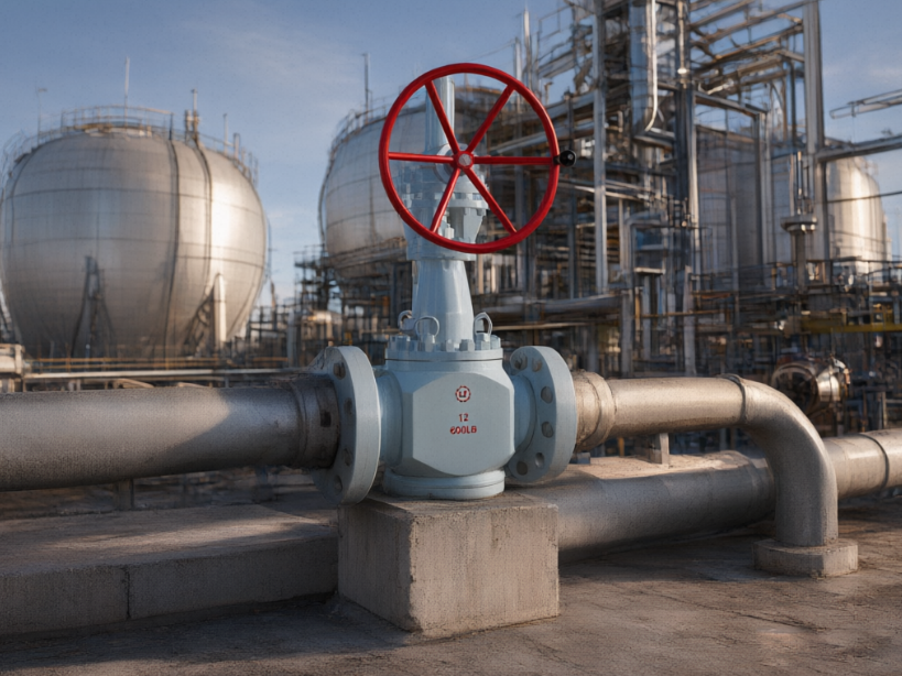
Debris is what scores a seat, and on a conventional ball valve it is trapped between ball and seat and dragged across both faces every stroke. Our Longz orbit ball valve tilts the ball clear before it turns, so nothing is trapped — flow carries particles through and scrubs the seat instead of grinding them into it. Closing is a separate action: a cam at the stem’s lower end wedges the seat home mechanically, so your seal does not depend on line pressure.
Automatic pressure relief structure of orbit ball valve
Your line has a medium, a pressure, a temperature and an existing flange set — and a catalogue valve rarely matches all four. Our Longz rising stem ball valve is built around them: body, bonnet, stem, cam, ball and seat trim are combined from different materials to suit your medium, and dimensions follow your connection requirements, not ours.
Your Trusted orbit ball valve supplier in China
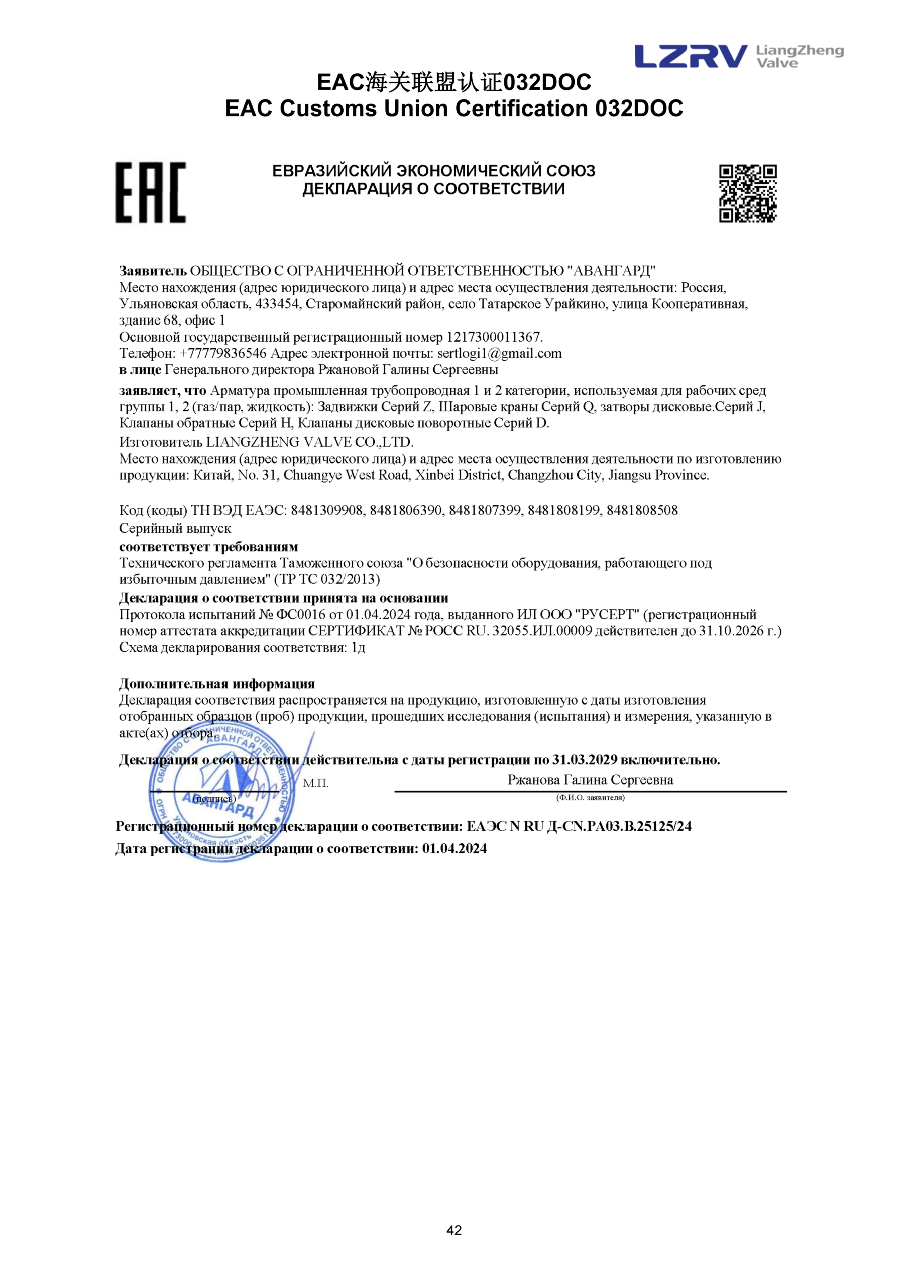
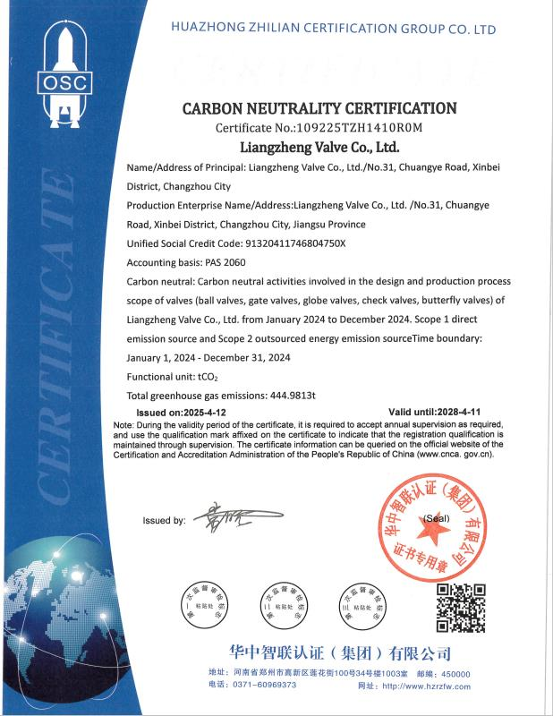
Longz has obtained ISO 9001 international quality management system certification, ISO 14001 environmental management system certification, API certification from the American Petroleum Institute, and other certificates confirming that its products meet domestic and international authoritative quality standards. The company also holds more than 50 invention patents and technology innovation patents.

- Dimensions of the Orbit Ball Valve
- certificate
| Nominal diameter | Structural form | Dimensions | Flange connection dimensions | Double-threaded | ||||||||||
|---|---|---|---|---|---|---|---|---|---|---|---|---|---|---|
| in | mm | L | H | h | W | D | D1 | D2 | T | f | n-d | Number | Thread | |
| GQ47H/Y150Lb NPS~10in(25~250mm);GQ547H/Y-150Lb NPS12~20in(300~500mm) | ||||||||||||||
| 1 | 25 | A | 216 | 285 | 255 | 160 | 108 | 79.5 | 51 | 12 | 7 | 4-15 | 4 | W1/2 |
| 1 1/2 | 40 | A | 216 | 325 | 290 | 200 | 127 | 98.5 | 73 | 15 | 2 | 4-15 | 4 | W1/2 |
| 2 | 50 | A | 216 | 345 | 305 | 200 | 152 | 120.5 | 92 | 16 | 2 | 4-19 | 4 | W5/8 |
| 2 1/2 | 65 | A | 241 | 385 | 340 | 250 | 178 | 139.5 | 105 | 18 | 2 | 4-19 | 4 | W5/8 |
| 3 | 80 | A | 282 | 445 | 400 | 250 | 190 | 152.5 | 127 | 19 | 2 | 4-19 | 8 | W5/8 |
| 4 | 100 | B | 305 | 485 | 430 | 300 | 229 | 190.5 | 157 | 24 | 2 | 8-19 | 8 | W5/8 |
| 6 | 150 | B | 403 | 620 | 560 | 350 | 276 | 241.5 | 216 | 26 | 2 | 8-22 | 8 | W3/4 |
| 8 | 200 | B | 502 | 710 | 630 | 450 | 343 | 298.5 | 270 | 29 | 2 | 8-22 | 8 | W3/4 |
| 10 | 250 | C | 673 | 850 | 770 | 350 | 406 | 362 | 324 | 31 | 2 | 12-25 | 12 | W7/8 |
| 12 | 300 | C | 762 | 1050 | 970 | 400 | 483 | 432 | 381 | 32 | 2 | 12-25 | 16 | W7/8 |
| 14 | 350 | C | 825 | 1230 | 1130 | 450 | 533 | 476 | 413 | 35 | 2 | 12-29 | 16 | W1 |
| 16 | 400 | C | 902 | 1520 | 1400 | 600 | 597 | 540 | 470 | 37 | 2 | 16-29 | 16 | W1 |
| 18 | 450 | C | 991 | 1610 | 1470 | 650 | 635 | 578 | 533 | 40 | 2 | 16-32 | 16 | W1 1/8 |
| 20 | 500 | C | 991 | 1680 | 1520 | 700 | 699 | 635 | 584 | 43 | 2 | 20-32 | 20 | W1 1/8 |
| GQ47H/Y300Lb NPS~10in(25~250mm);GQ547H/Y-300Lb NPS12~20in(300~500mm) | ||||||||||||||
| 1 | 25 | A | 216 | 285 | 255 | 160 | 124 | 89 | 51 | 18 | 7 | 4-19 | 4 | W5/8 |
| 1 1/2 | 40 | A | 216 | 325 | 290 | 200 | 156 | 114.5 | 73 | 21 | 7 | 4-22 | 4 | W3/4 |
| 2 | 50 | A | 216 | 345 | 305 | 200 | 165 | 127 | 92 | 23 | 7 | 8-19 | 8 | W5/8 |
| 2 1/2 | 65 | A | 241 | 385 | 340 | 250 | 190 | 149 | 105 | 26 | 7 | 8-22 | 8 | W3/4 |
| 3 | 80 | A | 282 | 445 | 400 | 250 | 210 | 168.5 | 127 | 29 | 7 | 8-22 | 8 | W3/4 |
| 4 | 100 | B | 305 | 485 | 430 | 300 | 254 | 200 | 157 | 32 | 7 | 8-25 | 8 | W3/4 |
| 6 | 150 | B | 403 | 620 | 560 | 350 | 318 | 270 | 216 | 37 | 7 | 12-29 | 12 | W3/4 |
| 8 | 200 | B | 502 | 710 | 630 | 450 | 381 | 330 | 270 | 42 | 7 | 12-32 | 12 | W1 7/8 |
| 10 | 250 | C | 673 | 850 | 770 | 350 | 445 | 387.5 | 324 | 48 | 7 | 16-35 | 16 | W1 1 |
| 12 | 300 | C | 762 | 1050 | 970 | 400 | 521 | 451 | 381 | 5 | 7 | 20-35 | 16 | W1 1/8 |
| 14 | 350 | C | 825 | 1230 | 1130 | 450 | 584 | 514.5 | 413 | 54 | 7 | 20-38 | 20 | W1 1/8 |
| 16 | 400 | C | 902 | 1520 | 1400 | 600 | 648 | 571.5 | 470 | 58 | 7 | 20-41 | 20 | W1 1/4 |
| 18 | 450 | C | 991 | 1610 | 1470 | 650 | 711 | 628.5 | 533 | 61 | 7 | 20-44 | 20 | W1 1/4 |
| 20 | 500 | C | 991 | 1680 | 1520 | 700 | 775 | 686 | 584 | 64 | 7 | 24-44 | 24 | W1 1/4 |
The process media flowing through our pipelines is corrosive, and there are temperature fluctuations. During selection, our primary concerns are the aging of sealing components and the erosion of sealing surfaces by the media. The valve seat of this valve can be equipped with either PTFE soft sealing or full-metal hard sealing. Based on the characteristics of the medium, we selected the hard sealing solution. The sealing surface has a thick enough weld overlay with substantial hardness and sufficient wear-resistant layer thickness. After more than two years of use,Almost no signs of erosion were observed during disassembly and inspection.
 EngineerSpanish Chemical Company
In our equipment area, the media contains particles and impurities. In the past, valves often became stuck due to scale buildup on the sealing surfaces. Maintenance required hot work and pipe disassembly, which involved open flames. This resulted in significant losses during each shutdown, causing substantial operational disruptions.The ball of the track ball valve first separates from the valve seat during opening and closing, allowing the fluid to flush along the sealing surface at 360°, resulting in a notably effective self-cleaning effect;The top-loading structure allows us to disassemble the valve cover and inspect or replace internal components online, without needing to detach the valve from the pipeline. This reduces the maintenance window by more than half.
 Procurement ManagerAmerican Gas Company
The most fundamental difference lies in whether the sphere comes into contact with the valve seat during the opening and closing process. Traditional ball valves, whether floating or fixed type, maintain constant contact between the ball and the valve seat, rotating via friction, resulting in high switching torque and continuous wear on the sealing surface; The track ball valve allows the ball to first detach from the valve seat before rotating, with no friction throughout the process, fundamentally solving the problem of seal surface wear.
The nominal diameter range is DN60~DN600, covering large-diameter requirements.
The operating temperature range of this Orbit Ball Valve varies depending on the material, spanning from -196°C to~600°C.
The main body materials of this orbit ball valve include A105, WCB, LF2, and other materials.
This Orbit Ball Valve is available in both soft-sealed and hard-sealed configurations.
Operating Principle of Track Ball Valve
Initiation process
In the closed position, the valve core is tightly pressed against the valve seat under mechanical force applied by the valve stem.
When the handwheel is turned counterclockwise, the valve stem moves upward, and its bottom angular surface causes the valve core to deviate from the valve seat.
The third valve stem continues to rise and interacts with the guide pins in the spiral groove of the valve stem, causing the valve core to begin rotating without friction
At the fully open position, the valve stem has risen to its limit position, and the valve core has also rotated to the fully open position.
Shutdown process
To turn it off, rotate the handle clockwise. The valve stem begins to descend and causes the valve core to start rotating. Continue to turn the handwheel. The valve stem, interacting with the guide pin embedded in the screw groove on it, causes both the valve stem and the valve core to rotate 90 degrees simultaneously. Near the end of its closure, the valve core has rotated 90 degrees without contacting the valve seat. During the final few rotations of the handwheel, the angular flat surface at the bottom of the valve stem mechanically wedges against the ball center, pressing it tightly onto the ball valve.