
Flange gate valve manufacturer in China
Our Longz flange gate valves are widely used in pipeline systems of industries such as petroleum, chemical and power. Although their structure is relatively complex and the opening and closing stroke is large, they still have advantages such as low fluid resistance, easy operation, and unrestricted flow direction.

Our concealed rod flange gate valve is designed to be sealed off from the outside, preventing shock waves and nuclear, biological and chemical warfare agents from entering the engineering area through the pipeline. It can be widely used in fluid pipelines of petroleum and chemical systems as a shut-off device. The concealed rod flange gate valve features a valve stem that rotates to drive the gate plate to open and close, thus requiring a small installation space.
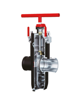
Our flat gate valve ensures complete isolation of the pipe network passage from the valve chamber when fully open or fully closed. The valve seat sealing component is completely covered by the gate plate, preventing impurities, dust, tar, and air flow from damaging and eroding the sealing component, effectively guaranteeing the sealing performance of the valve and prolonging its service life.

Our Semi Enclosed Flange Gate Valve operates by the movement of the valve stem, which drives the gate to open and close. Therefore, the opening degree of the gate can be determined by observing the height to which the valve stem rises.
The sealing of the Flange gate valve
Our flange gate valve mainly serves the function of reliable shut-off in the pipeline system. When closed, the gate plate can closely adhere to the valve seat, forming a stable seal, thereby reducing the risk of medium leakage. When fully open, the flow channel approximates the straight pipe section of the pipeline, resulting in low flow resistance and low pressure loss. It is also connected by flanges, making installation, alignment and fixation relatively convenient, and making subsequent maintenance and replacement more straightforward. The overall structure has high strength and can withstand pipeline stress and vibration, making it suitable for long-term operation in industrial pipelines such as water supply, fire protection, and chemical industries.
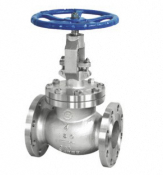
Your Trusted flange gate valve supplier in China


As a manufacturer specializing in valves, we have over 20 years of experience in designing and manufacturing valves. We have fully utilized our independently developed advanced MES intelligent manufacturing management system (LMES) to manage the product process and quality traceability, achieving professional, automated, standardized and procedural production organization.

In the chemical , when our Flange gate valve is fully open, the gate plate withdraws from the flow channel, resulting in a small pressure drop. For large-diameter pipelines, it saves pump power. When the sealing surface is in good condition, the cutting function is clear. The flange connection is convenient for disassembly and assembly, and it has good pressure resistance and vibration resistance performance.
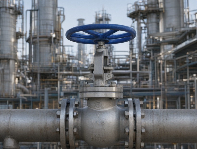
Our flange gate valves are mainly installed on various pipelines for transporting water, steam and condensate in the power industry. They perform the core function of fully opening or fully closing the medium, facilitating the operation, isolation and maintenance of related equipment.
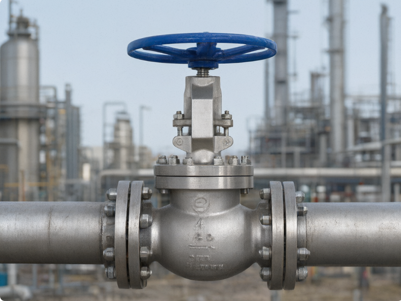
In the petroleum industry, our Flange gate valve has low resistance for the medium to pass through. The flange connection is also convenient for installation, disassembly and maintenance, and it is also easy to connect and cut off the materials.

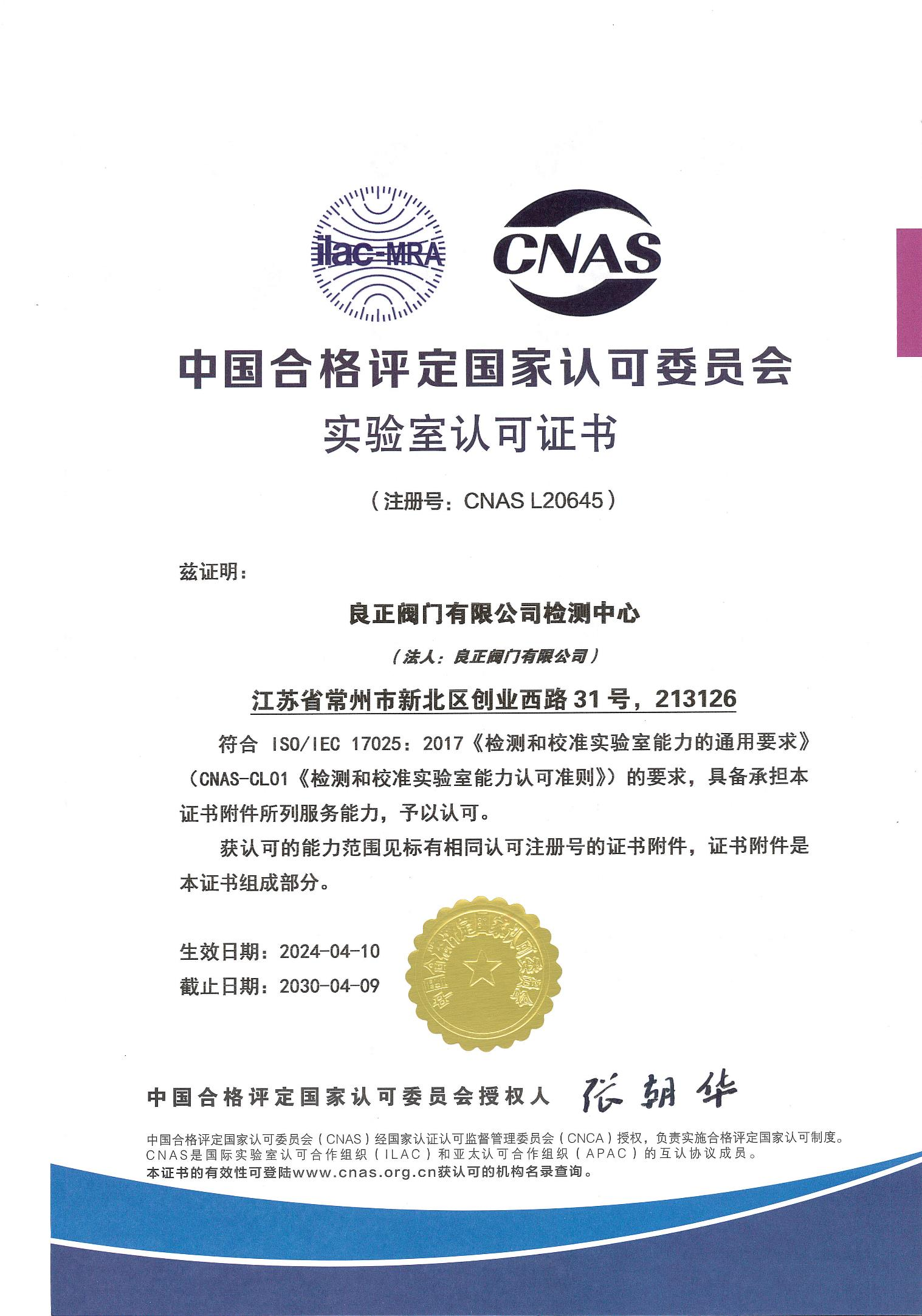
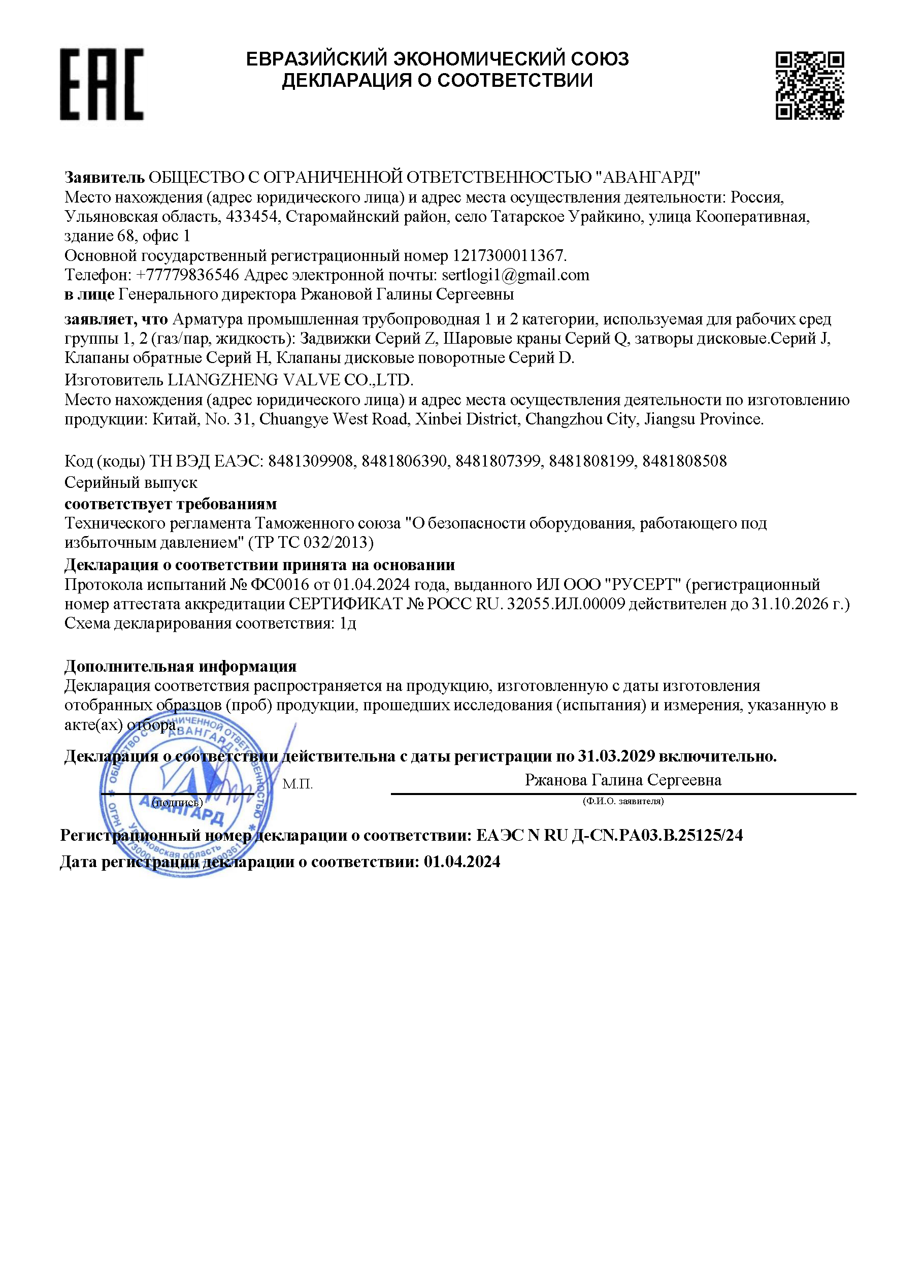
- certificate
- Dimension Chart for Flange Gate Valves
| DN | L | D | D1 | D2 | b | n-Φd | W | H | |
|---|---|---|---|---|---|---|---|---|---|
| Class 300 | |||||||||
| 1/2″ | mm | 152 | 95 | 66.5 | 35 | 15 | 4-15 | 125 | 190 |
| in | 5.98 | 3.74 | 2.62 | 1.38 | 0.59 | 4-0.59 | 4.92 | 7.48 | |
| 3/4″ | mm | 178 | 117 | 82.5 | 43 | 16 | 4-19 | 125 | 212 |
| in | 7.01 | 4.61 | 3.25 | 1.69 | 0.63 | 4-0.75 | 4.92 | 8.35 | |
| 1″ | mm | 203 | 124 | 89 | 51 | 18 | 4-19 | 160 | 231 |
| in | 7.99 | 4.88 | 3.50 | 2.01 | 0.71 | 4-0.75 | 6.30 | 9.09 | |
| 1 1/2″ | mm | 229 | 156 | 114.5 | 73 | 20.7 | 4-22 | 200 | 391 |
| in | 9.02 | 6.14 | 4.51 | 2.87 | 0.81 | 4-0.87 | 7.87 | 15.39 | |
| 2″ | mm | 267 | 165 | 127 | 92 | 22 | 8-19 | 200 | 406 |
| in | 10.51 | 6.50 | 5.00 | 3.62 | 0.87 | 8-0.75 | 7.87 | 15.98 | |
| 2 1/2″ | mm | 292 | 190 | 149 | 105 | 25 | 8-22 | 240 | 457 |
| in | 11.50 | 7.48 | 5.87 | 4.13 | 0.98 | 8-0.87 | 9.45 | 17.99 | |
| 3″ | mm | 318 | 210 | 168.5 | 127 | 29 | 8-22 | 280 | 470 |
| in | 12.52 | 8.27 | 6.63 | 5.00 | 1.14 | 8-0.87 | 11.02 | 18.50 | |
| 4″ | mm | 356 | 245 | 200 | 157 | 32 | 8-22 | 320 | 590 |
| in | 14.02 | 9.65 | 7.87 | 6.18 | 1.26 | 8-0.87 | 12.60 | 23.23 | |
| 6″ | mm | 444 | 318 | 270 | 216 | 37 | 12-22 | 500 | 711 |
| in | 17.48 | 12.52 | 10.63 | 8.50 | 1.46 | 12-0.87 | 19.69 | 27.99 | |
| 8″ | mm | 559 | 381 | 330 | 270 | 41 | 12-25 | 500 | 750 |
| in | 22.01 | 15.00 | 12.99 | 10.63 | 1.61 | 12-0.98 | 19.69 | 29.53 | |
| 1/2″ | mm | 165 | 95 | 66.5 | 35 | 15 | 4-15 | 160 | 285 |
| in | 6.50 | 3.74 | 2.62 | 1.38 | 0.59 | 4-0.59 | 6.30 | 11.22 | |
| 3/4″ | mm | 190 | 117.5 | 82.5 | 43 | 16 | 4-19 | 160 | 285 |
| in | 7.48 | 4.63 | 3.25 | 1.69 | 0.63 | 4-0.75 | 6.30 | 11.22 | |
| 1″ | mm | 216 | 124 | 89 | 51 | 18 | 4-19 | 160 | 313 |
| in | 8.50 | 4.88 | 3.50 | 2.01 | 0.71 | 4-0.75 | 6.30 | 12.32 | |
| 1 1/2″ | mm | 241 | 156 | 114.5 | 73 | 23 | 4-22 | 240 | 365 |
| in | 9.49 | 6.14 | 4.51 | 2.87 | 0.91 | 4-0.87 | 9.45 | 14.37 | |
| 2″ | mm | 292 | 165 | 127 | 92 | 25 | 8-19 | 240 | 444 |
| in | 11.50 | 6.50 | 5.00 | 3.62 | 0.98 | 8-0.75 | 9.45 | 17.48 | |
| 2 1/2″ | mm | 330 | 190 | 149 | 105 | 29 | 8-22 | 240 | 483 |
| in | 12.99 | 7.48 | 5.87 | 4.13 | 1.14 | 8-0.87 | 9.45 | 19.02 | |
| 3″ | mm | 358 | 210 | 168.5 | 127 | 32 | 8-22 | 280 | 533 |
| in | 14.09 | 8.27 | 6.63 | 5.00 | 1.26 | 8-0.87 | 11.02 | 20.98 | |
| 4″ | mm | 406 | 273 | 216 | 157 | 38.1 | 8-25 | 360 | 622 |
| in | 15.98 | 10.75 | 8.50 | 6.18 | 1.50 | 8-0.98 | 14.17 | 24.49 | |
| 6″ | mm | 459 | 356 | 292 | 216 | 47.7 | 12-29 | 500 | 800 |
| in | 18.07 | 14.02 | 11.50 | 8.50 | 1.88 | 12-1.14 | 19.69 | 31.50 | |
| 8″ | mm | 597 | 419 | 349 | 270 | 55.6 | 12-32 | 550 | 927 |
| in | 23.50 | 16.50 | 13.74 | 10.63 | 2.19 | 12-1.26 | 21.65 | 36.50 | |
This flange gate valve is really stable to use. It performs exceptionally well during production and maintenance, and the pipeline pressure remains consistently balanced. I have been using it for a whole year and haven’t seen any leaks. It also has excellent corrosion resistance.
 EngineerMexican Chemical Company
This type of flange gate valve has been in operation here for quite some time. The sealing is very reliable and no leakage has been detected. It is very convenient for maintenance, and the disassembly and inspection process is effortless
 Purchasing DepartmentSouth African Oil Company
The flange gate valve itself is bidirectional sealed and the medium can flow in both directions. Generally, there is no flow direction restriction. However, the valve stem should be installed vertically upwards. Horizontal or inverted installation of the valve stem will cause the gate plate to wear unevenly and the packing to be stressed unevenly, which is prone to leakage. If space constraints require inclined installation, the inclination angle should not be too large and it should be specified when placing the order.
Perform one opening and closing operation regularly to prevent the gate plate from getting stuck; check the valve stem threads for lubrication; inspect the tightness of the flange bolts; for outdoor-installed valves, regularly check the coating and rust. For valves that have not been operated for a long time, it is recommended to activate them once every quarter.
The main material of this flange gate valve is: A105N, LF2, LF3, etc.
The working principle of the flange gate valve
The opening and closing of a flange gate valve is achieved by rotating the handwheel or the driving device, which in turn drives the valve stem to rotate. The valve stem typically features a trapezoidal thread that engages with the nut on the valve cover, converting the rotational force into axial thrust, thereby driving the gate plate to perform linear up-and-down movement along the valve seat. When the gate plate moves upward and leaves the valve seat and reaches a certain height (usually one times the valve diameter), the fluid passage is completely unobstructed, and the valve is in the fully open state. Conversely, when the gate plate moves downward and presses against the valve seat, the fluid passage is cut off, and the valve is in the fully closed state. Flange gate valves mainly rely on forced sealing or self-sealing mechanisms to ensure sealing performance. Most flange gate valves are of the forced sealing type. When the valve is closed, an external force (such as the handwheel or electric device) is used to forcibly press the gate plate against the valve seat, causing the sealing surfaces to closely adhere, thereby preventing the leakage of the medium. Some medium-pressure and high-pressure gate valves utilize the lateral force generated by the medium pressure to assist in sealing, which is the self-sealing mechanism. When the medium pressure increases, the resultant force exerted by the medium on the gate plate causes it to press more tightly against the valve seat, thereby improving the sealing effect and being suitable for high-temperature and high-pressure working conditions.